FalCon S1-c
A Next Gen Model Rocket

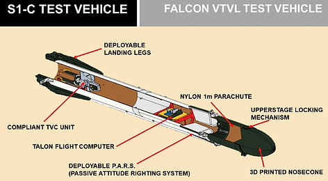
S1-C Layout

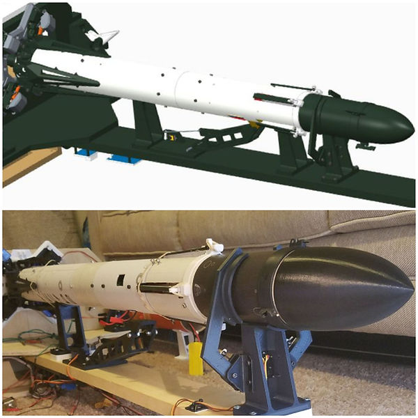
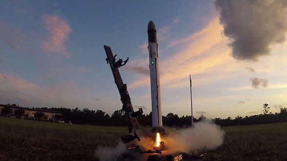
S1-C is the 3rd revision of 1st stage Falcon 9 style rockets I've developed. It is the testbed on which all future rocket parts can be developed, flown and improved. The air-frame is a 75mm tube with a coupler in the center so that it can be broken in half and serviced easily. The smaller tube diameter is significantly lighter than the 98mm size and makes it much more efficient for E and F class motors. Weight is approximately 700 grams.
S1-C features a parachute recovery system, deployable landing fin prototypes, and deployable landing legs with a modular system for trying multiple materials and structures. The vehicle is intended to test all hardware, processes and flight modes leading up to a propulsive landing.
It has served to test and improve the TVC system over multiple iterations and improvements.


CONCEPT TO REALITY
Born in CAD, the rocket was refined by printing, assembling, and then refining parts through multiple passes. Each new revision reduced weight, increased strength, and made better use of the 3D printing medium.
It is also the first of my rockets to use completely custom flight controller and self-written flight software. It was also the first rocket to fly off the upgraded launch pad. The design was highly fluid with revisions on every part focusing on the future capability of landing.
The design was the first to use a 75mm tube to decrease the weight and lead to a whole new line of hardware intended for this size vehicle.
HARDWARE MEETS SOFTWARE
Computer development
The flight computer was prototyped using a soldering breadboard with 3 versions before it was used for flight. The initial version had 2 pyrotechnic channels with later expansion to 4 channels.
Due to a lack of reliability and a high reject rate, the solder breadboard approach was less than desirable. I quickly moved to a printed circuit board designed to hold all the components. This opened the door to extra pyrotechnic channels.
The finished flight computer featured:
-
BNO055 Inertial Measurement Unit
-
BMP388 Precision Altimeter
-
4x N Channel 32 Amp MOSFET
-
6 Channel Expansion Port
-
2 Servo Outputs
-
16 MHz Adafruit Metro Mini Micro Controller
The main disadvantage of this computer was it's lack of logging capability. This feature is a future expansion.
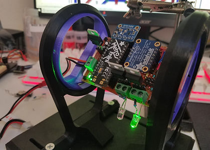
1st Flight Operational Computer. Used for the first 4 Flights of the vehicle

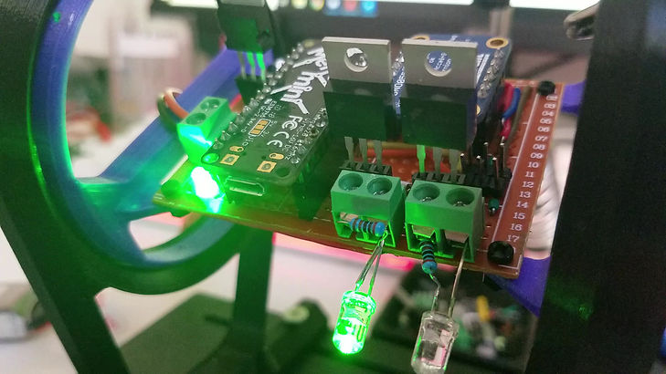
TALON V1.0 prototype printed circuit board flight computer
The prototype flight computer sending vectoring commands to the TVC gimbal. The LED represent the pyrotechnic channel outputs and light up when the computer is pushed over 45 degrees. This represents triggering an in-flight abort. The flight termination system FTS ends the flight by deploying the parachute if the computer detects things go off axis.
FLIGHT TESTING


_JPG.jpg)