space launch system
(sls)
SPACE
LAUNCH
SYSTEM


A BRAND NEW PROJECT
Starting a project is never easy. It usually requires lots of inspiration, creative thinking, and lot, and lots of problem solving. The inspiration side of things was easy, at my day job I saw the SLS (Space Launch System) every day so that choice was obvious. Additionally the fact my designs were far too heavy to fly on a single motor also pushed things that way.
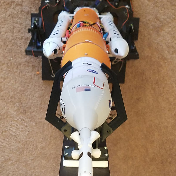
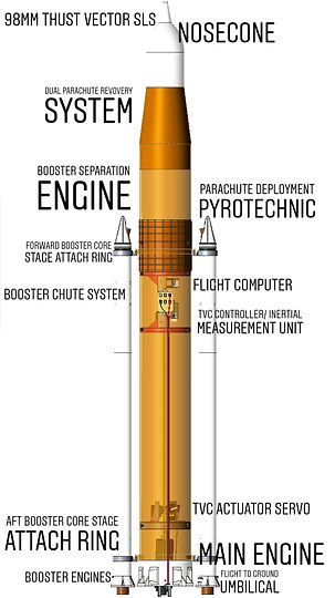
SLS is comprised of several elements, a core stage - the smart orange bit in the center. On the actual thing this section runs on liquid hydrogen and oxygen, and majors in being huge. Proportionally, the 4 inch tube I had already bought matched the SLS as well.
Next is the 2 boosters on either side of the SLS My first guess was these could be made to be simple strap-on engines to provide that little extra thrust to get the whole beast off the ground without any extra control systems.
Finally there's the payload section of SLS. The real vehicle is comprised of an upperstage and the whole Orion Spacecraft. I opted to make this a nosecone and parachute tube but short on funds I used a re-purposed nosecone from a 3 inch cert rocket.
BLOCK 1
BLOCK 2

The eventual goal was to move to a better looking and higher performing vehicle. Block 2 would feature the new custom flight computer in development while Block 1 tested the hardware needed for TVC flight. Block 2 would have a host of improvements.
-
Better TVC
-
Stronger Booster Engines
-
More Scale Look
-
Custom Flight Computer
-
Advanced 1 Axis TVC Boosters
-
Advanced Modular Launch Pad
-
Intended for upgrade to 2 stage
The Block 1 would pave the way to the more advanced Block 2. This incremental development approach helped get some early success and let me stay in the project and see it through
DIFFICULTIES
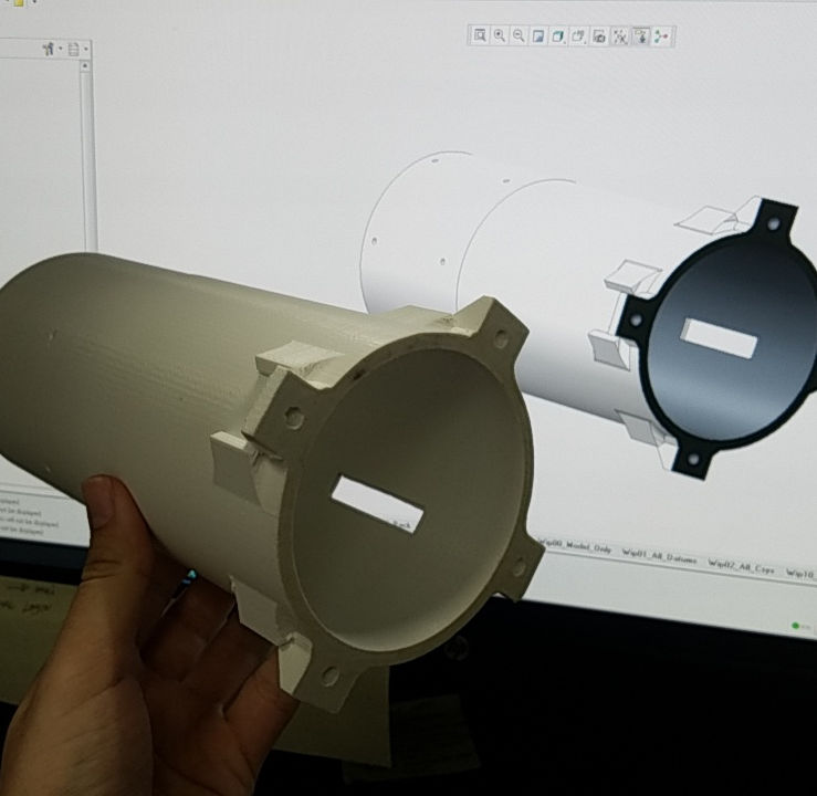
A few things became evident early on. First was the fact that this was going to become very expensive very fast. Rocket engines weren't cheap so there was a big incentive to using only 1 per flight. The SLS design blew that out of the water. The start up cost of buying all new screws, wire, soldering equipment, and spares also slowed progress at first. On top of all of this I had been using a contractor service for 3D prints which really made things slow down. First payoff was when the TVC Unit made its first movement. That's when the project seemed viable.
The thrust vector system was controlled by a re-purposed quadcopter controller with PID control loops running on the Roll and Pitch axes of the controller


FLIGHT PLAN
The Rocket is built around the use of an Apogee F10 Long burning main engine. The engine burns for 7 seconds meaning the boosters must fall away before the core stage engine stops burning. Boosters are separated using reverse facing A engines intended to kick the boosters off the core stage as they burn out. The Core engine acts to steer the rocket and maintain course until it reaches apogee. An on board barometer detects the altitude change become negative and triggers a pyrotechnic in the upper section of the rocket. This means if the rocket goes out of control, the chutes will automatically bring the rocket down safely.

POST FLIGHT ANALYSIS
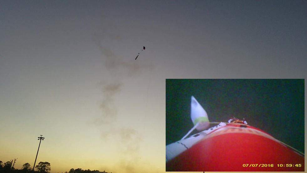
The first flight of the model was a mixed bag. Ground and flight systems communicated successfully and initiated the launch of the vehicle with all three engines firing simultaneously. The thrust vector control system performed perfectly keeping the vehicle on track and activating a small pitch maneuver.
The boosters however failed to separate. The booster fit to the core stage was not rigid enough to where it produced a rotation over the flight. The fit between the boosters was too tight to fully separate and on burnout the vehicle began flipping end over end. The issue was detected by the barometer and the recovery system was successfully triggered. Overall the flight was a success with the vehicle returning in tact and the TVC system acting to control the rocket.
